


|
KMG Grinder Jigs and Attachments
 |
|
|
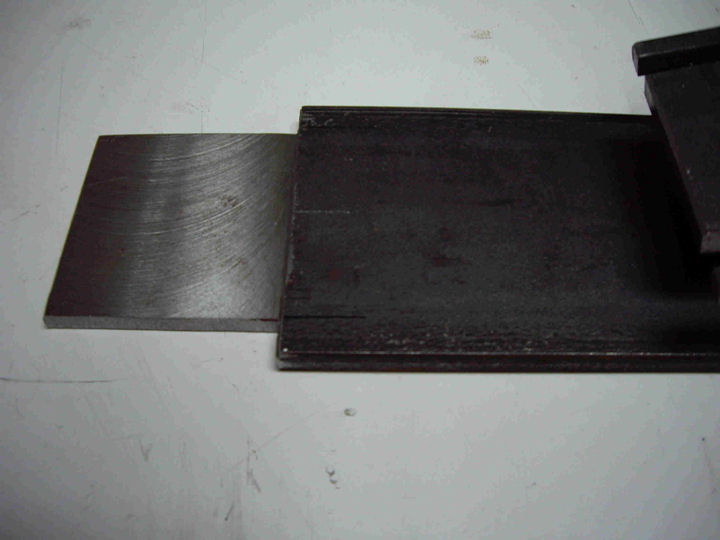
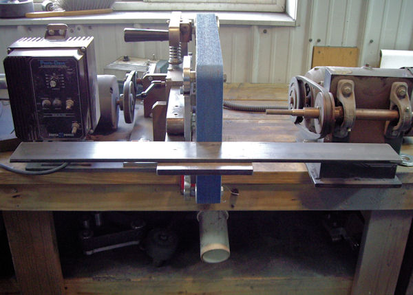
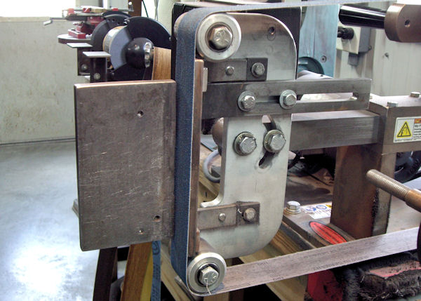
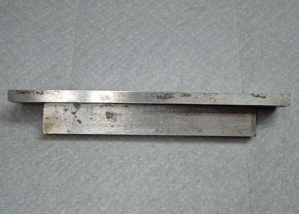
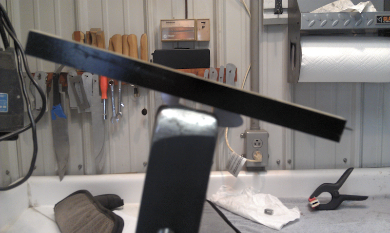
Integral Grinding Attachment
The platen is ¼” x
3” x 12” that has been cut down at the end that fits into the
small wheel fork. The end that fits between the fork is 2
¼” x 2”. That area has been milled down on the back side
to a thickness of 3/16” to allow it to match the top radius of
the ½” wheel. You will also have to file out the corners
of the small wheel fork slightly, so the platen can fit
properly.
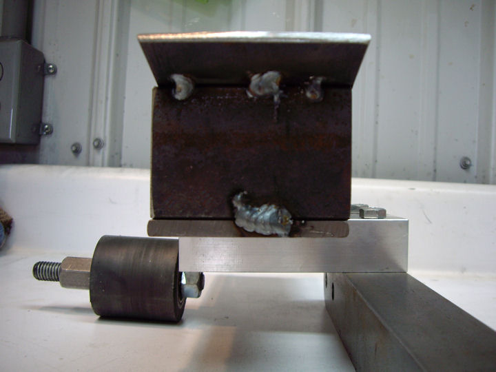
The angle iron “riser” piece is 2” x 2” angle iron. My
“riser” is welded about 1 3/8” from the end of the platen.
That is the distance (on my machine) that positions the platen
to fit under the belt. You want the belt to lie smoothly
on the top of the platen, so position your riser to lift the
belt slightly as it runs over the top end of the platen.
The base plate is ¼” x 3” x 5” with two 1” long slots milled
into it for the attaching bolts. I drilled and tapped two
¼” x 20 holes in the top of the small wheel fork to attach the
platen.
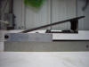
To attach the platen to the machine; slide it onto the attaching
bolts and move it into a position that matches the top of the
wheel (I use a straight edge to check) then tighten it down.
|
|
|
|
|
|
|
|
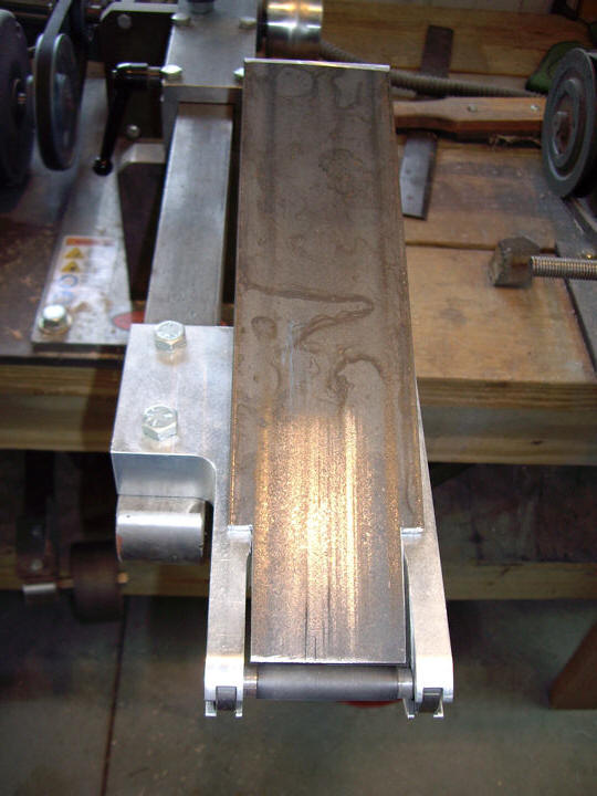
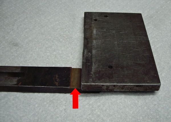
Clip Grinding Attachment
The work plate on the clip grinding attachment is 4” X 20” X ¼” steel. The brackets
are made from 3” X 3” X ¼” angle iron. The arm to attach it to
the KMG is 1 ½” X ½” X 10”.
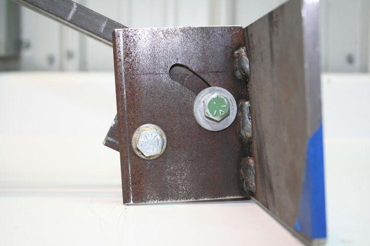
A 3/8” slot is milled in the arm that attaches the fixture to
the KMG. The fixture doesn’t need a long range of motion, so
you only need to make two shorter slots centered over the
attaching bolt holes.
The angle iron brackets were clamped together and two holes were
drilled of the size required for tapping 3/8 X 16 thread holes.
The two holes in the bracket for the work plate were drilled out
to 3/8”, and the holes in the bracket for the attachment arm
were tapped with 3/8 X 16 threads. The attachment arm
bracket was clamped in the vice on the milling machine and the
work plate
bracket was bolted to it through the pivot bolt hole. The bolt
between the two parts was left loose enough so the work plate
bracket could move. A 3/8” end mill was lowered into
the other hole in the work plate bracket, the mill turned on and a Crescent
wrench was used to crank the bracket into the end mill and cut
the curved slot for the adjustment bolt.
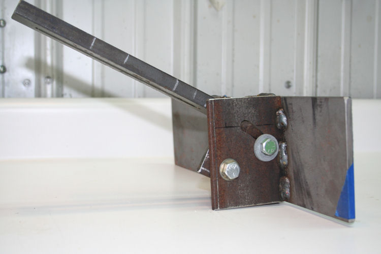
Bolt the attachment arm to the KMG. Assemble the brackets
and the work plate and hold them in place with C-clamps.
After squaring everything up, tack weld the parts together.
Take it off of the KMG and weld it together solidly. DO
NOT overdo the welds!!! This fixture does not take a lot
of pressure in use, so it doesn’t need huge welds. The
long piece of steel that the work plate is made from will probably warp when you weld it. The
more you weld, the more it warps and it will have to be
straightened.
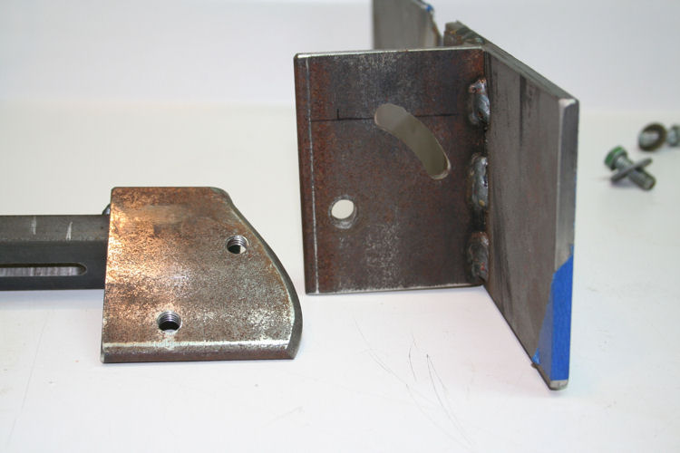
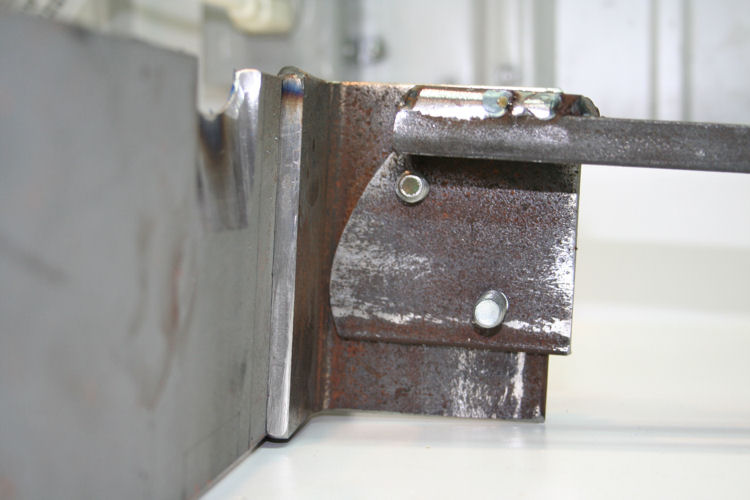
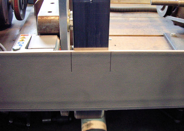
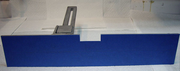
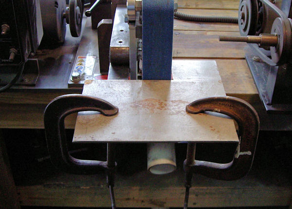
Once the attachment
is welded together, the
unit will need to be fitted to your machine by installing it in
front of your flat platen and marking it to saw and grind a
section out to fit around the flat platen. Install the
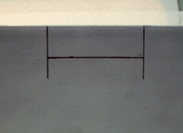
attachment to your grinder and make marks on the work plate, about an eighth of an
inch outside both edges of your flat platen; laying out vertical
lines about 2 1/4" apart.
Draw a horizontal
line between the two vertical lines, and about 3/4" below the
top of the work plate. Saw out this rectangle area.
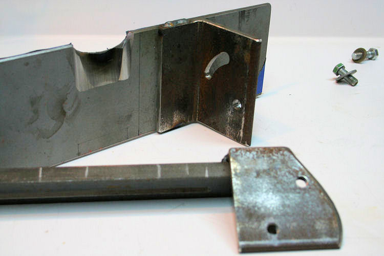
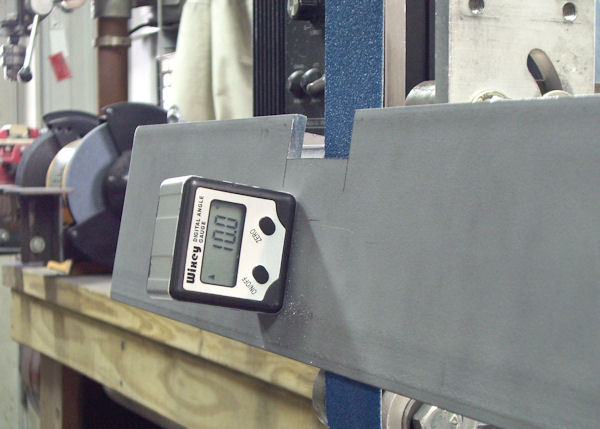
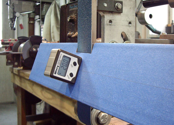
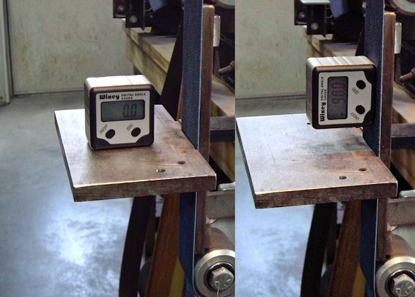
Put the
attachment on the grinder and set the angle of the work plate to
about 10 degrees.
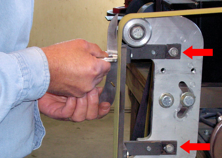
Loosen the
mounting bolts slightly, so you can slide the attachment. Start
the grinder and push the attachment into the running belt to
grind the back side of the work plate. This will relieve the
back of the plate so that when you use the attachment, the face
of the belt will be close to the front surface of the plate. Grind into the back of the plate until there is about an
1/16" lip left at the front.
Use a file to
clean out the corners of the relieved
area.
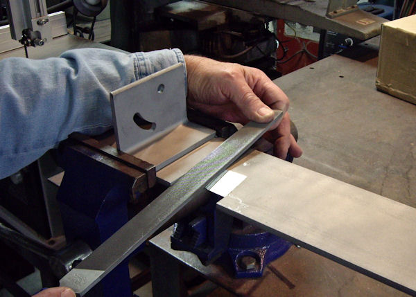
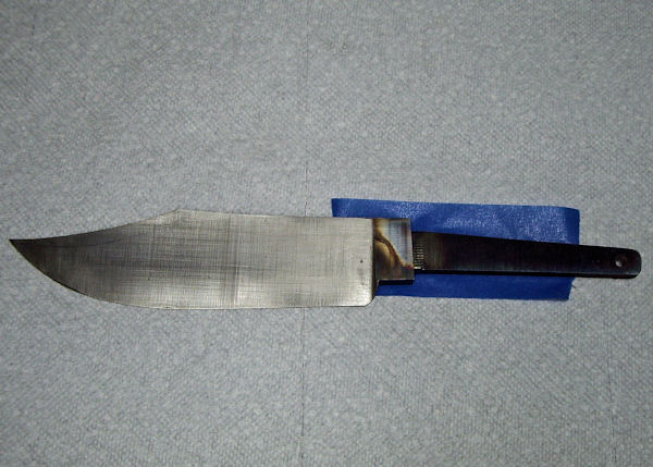
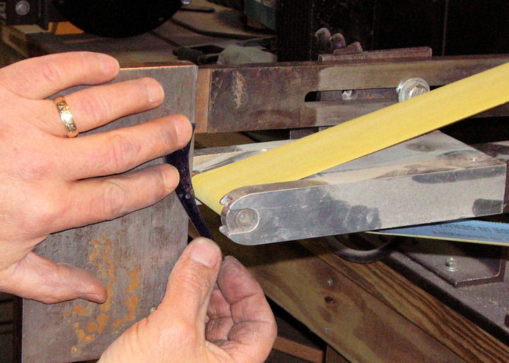
I have put
painter's tape over the work plate on my attachment to protect
the blade from scratching. Other materials could be used; and
may work better too. I've heard that it was possible to have
things ceramic coated. Ceramic coating is very hard and slick.
This may be a good option.
The sharp corners
at the back of the riccasso tend to dig into the painters tape
on the work plate. I have found that it helps to also put tape
on the back of the blade.
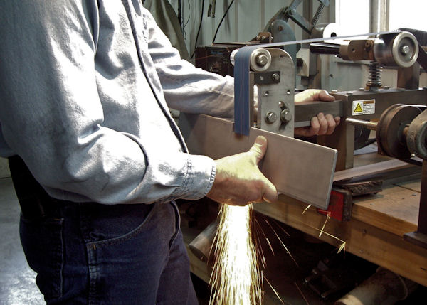
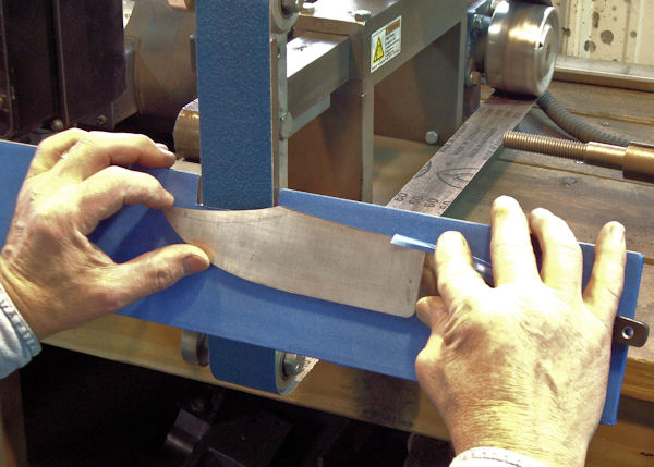
Install the
attachment to the grinder and set the angle that you wish to use
for grinding the blade clip. 20 degrees is often a good angle
to use for bowie knives.
To use the
attachment, hold the knife blade down against the surface of the
work plate at the riccasso. Raise the front of the blade up
into contact with the grinding belt.
|
|
|
|
Shop Jigs and Fixtures
|
|
|
|
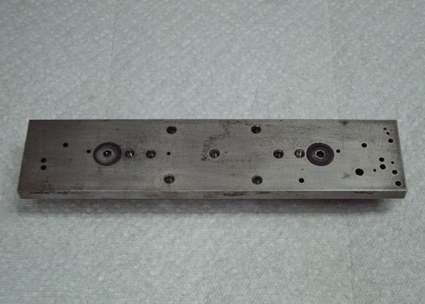
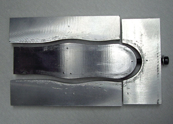
This is the most used fixture in my shop.
It has been used for drilling precise vertical holes, holding
parts for milling and a multitude of other uses. It has
threaded holes for attaching clamps to hold parts and also
precisely placed holes to pin two folder handles to it for
milling.
This jig is made from two
pieces of precision ground bar stock. The two pieces are
bolted together and are made to set in the jaws of my milling
machine vice. The tops of the milling machine vice jaws
are surface ground flat and square with the top of the milling
machine table. This jig will set on top of the vice jaws
and provide a work surface that is square with the milling
machine table.
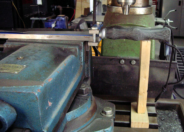
One of my uses for this jig
is to drill pin holes through the handle material and tang of a
knife. The knife, with the handle glued on, is clamped to
the jig at the riccasso. A piece of wood is used with a
tapered wedge to support the handle so the pressure from the
drill doesn't cause it to flex downward. |
|
|
|
|
|
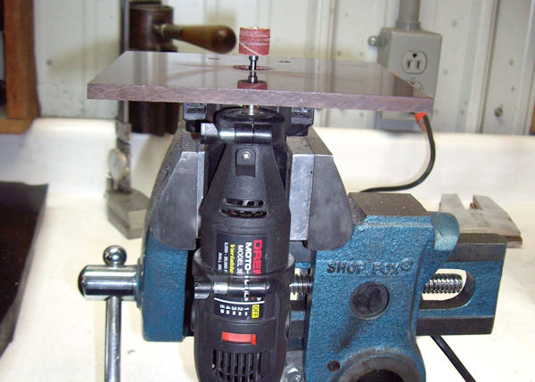
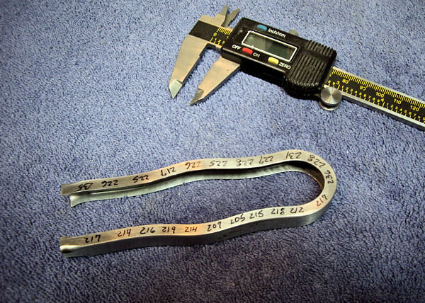
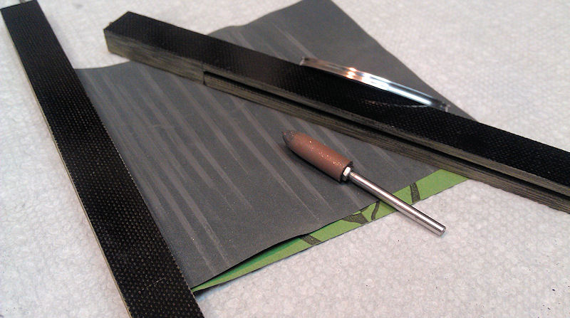
This is a set of tools that I made for
cutting a groove around an oval guard. They are made
of 3/8" micarta, cut to 7 3/4" long and 5/8" wide. An
1/8" slot is milled all the way through the micarta,
stopping a short distance from each end. Both ends of
the micarta piece have an 1/8" hole drilled into the slot.
A 1/8" chain saw file is inserted in one piece of micarta
and an 1/8" piece of drill rod is inserted into the other
micarta piece. The tool with the
file inserted, is slipped over the edge of the guard and
used to cut the groove. A piece of sandpaper is
wrapped around the drill rod in the other tool and used to
sand out the file marks. A bullet shaped Cratex point
is held in a pin vice and used to polish the bottom of the
groove. This tool makes it possible
to cut a perfectly centered groove around the guard and
easily finish the bottom of the groove. |
|
|
|
Hydraulic Press
Modifications and fixtures on a Riverside Machine
Shop hydraulic press.
|
|
|
|
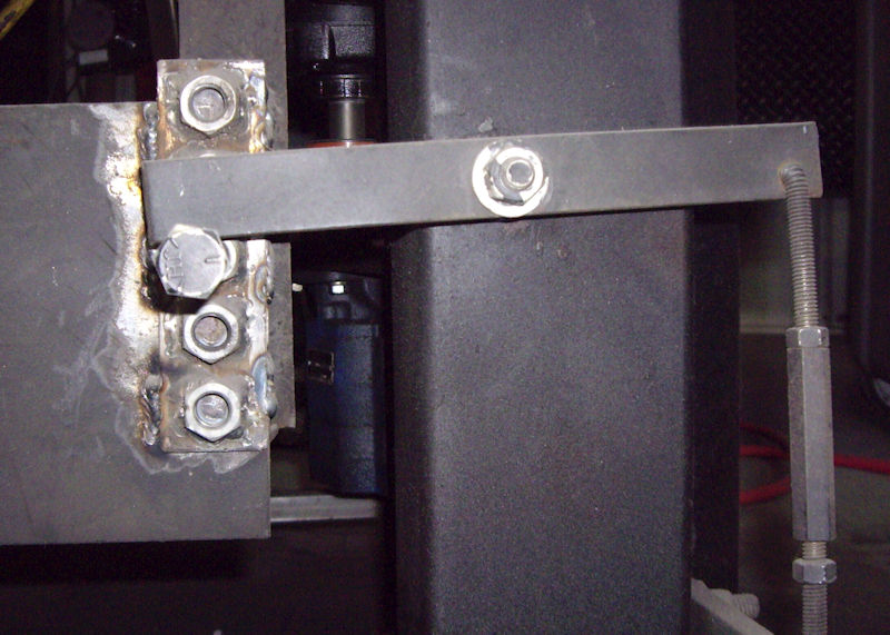
Modification to a Riverside Machine Shop
hydraulic press. Five nuts are welded to a strip of steel. The
strip is welded to the press ram. By moving the bolt between the
nuts, the ram can be adjusted so that it does not return all of
the way to the top of the stroke.
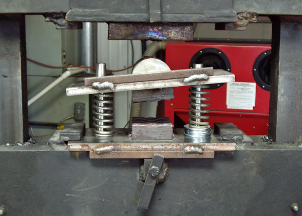
This is a set of pattern dies, set up in a spring
loaded fixture. The bottom pattern die is fixed and the top die
sets on springs. With this fixture, a damascus knife blade's
bevels can be forged in, before pressing the blade with pattern
dies. This will give a cleaner damascus pattern from the blade's
spine, all the way out to the cutting edge. Washers are
placed around the fixture's guide pin on one side, to angle the
top die to match the forged in blade bevels. |
|
|
|
Propane Forges
The concept of my forge design, is to cast a forge body out of a tough
structural refractory. Then, insulate this forge body by wrapping it in
ceramic wool. This places the fragile ceramic wool on the outside of
the forge body, where it is protected and it also minimizes the
hazardous wool fibers from being blown into the air by the blast of the
forge blower. I have never had to rebuild my forges because of the
refractory being damaged in use.
|
|
|
|
|
|
|
|
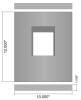
Forge Front View
|
|
|
|
Forge Left Side Cut-Away
|
|

|
|
Forge Right Side Cut-Away
|
|
|
|
Forge Top View
|
|
|
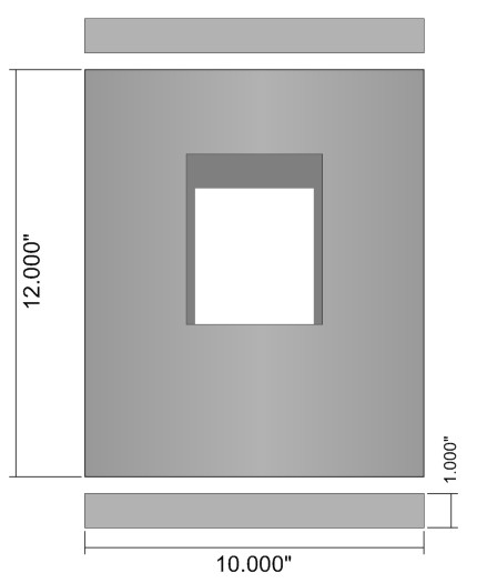
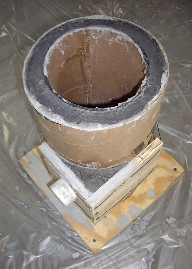
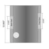
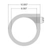
These are sketches of the
cast forge body for a vertical forge. The casting is of Mizzou Plus refractory. The
body is 12 inches tall and 10 inches in diameter on the
outside. The interior is 8 inches in diameter. The forge body
walls are approximately 1 inch thick. The top and bottom
pieces of the forge are 1 inch thick plates of Mizzou Plus.
Mizzou mixes and casts just like concrete. Once
set, it is also as tough as concrete. So, no worries about
damaging your forge refractory from jabbing it with your work
piece. Also, Mizzou is not damaged by forge welding flux.
Mizzou is a structural refractory; not an insulating
refractory. When running the forge, the cast Mizzou forge body
will heat up to the operating temperature of the forge. The
ceramic wool overwrap, is what provides the insulation for this
forge design.
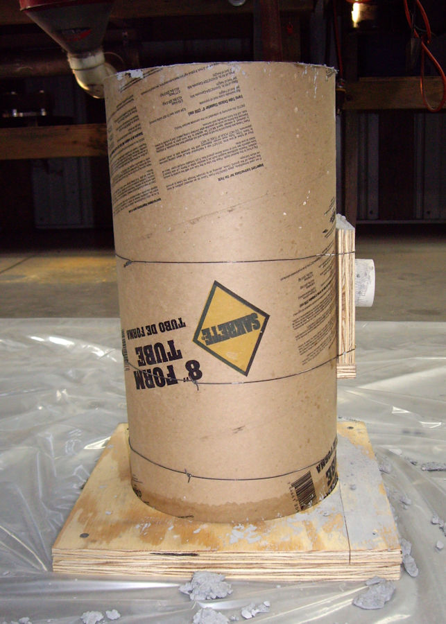
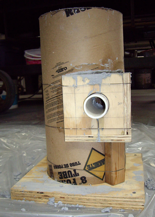
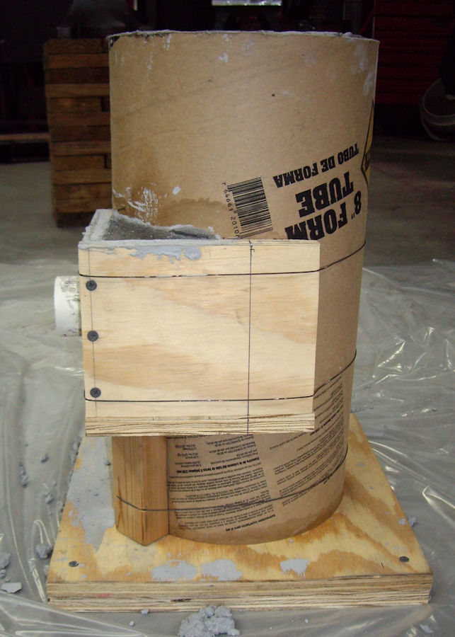
The forge body was cast
using cardboard forms for concrete piers. Door openings were
cut through both forms. Pieces of wood were cut from 2x6 boards
to block out the door openings. The wood blocks were inserted
through both forms during casting. This helps to stabilize the
forms and shape the door openings. When cutting the wood
blocks, put a slight taper on the edges of the blocks, towards
the interior of the forge. This helps with removal of the
blocks from the cured refractory.
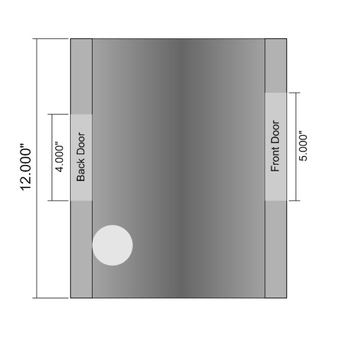
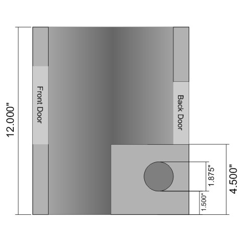
The flame opening was formed
using a piece of 1 1/2 inch PVC pipe. The resulting flame
opening is 1 7/8 inches in diameter. The bottom of the flame
opening is 1 1/2 inches above the bottom of the forge. I cast a
4 1/2 inch tall, rectangular block around the flame opening for
additional strength. This may not be necessary.
Both forge door openings are
4 inches wide. The front door is 5 inches tall. The back
door is 4 inches tall. The bottom of the doors are 4 1/2 inches
above the bottom of the forge.
The cast forge body is
overwrapped with 1 inch thick, 8 pound Inswool.
|
|
|
|
|
|
|
|
|
|
|
|
Large Vertical Forge
|
|
|
|
Large Vertical Forge 2
|
|
|
|
Large Vertical Forge 3
|
|
|
|
Forge Stand
|
|
|
|
Forge Work Rest
|
|
|
|
|
|
Forge Work Rest Slider
|
|

|
|
Forge Work Rest Vice
|
|

|
|
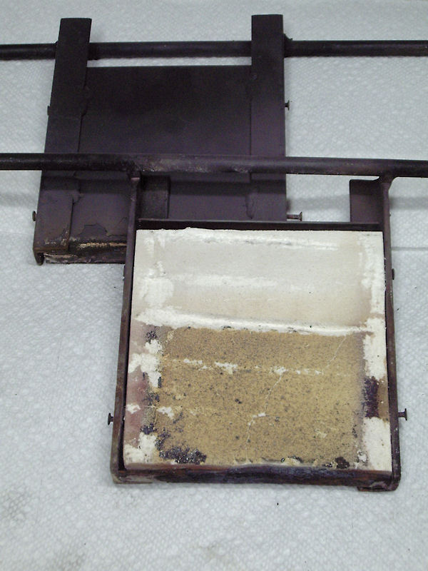
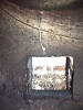
Forge Doors
|
|
|
|
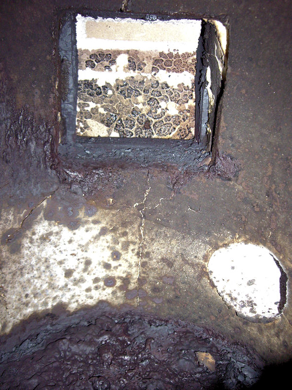
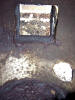
Forge Interior Bottom
|
|
|
|
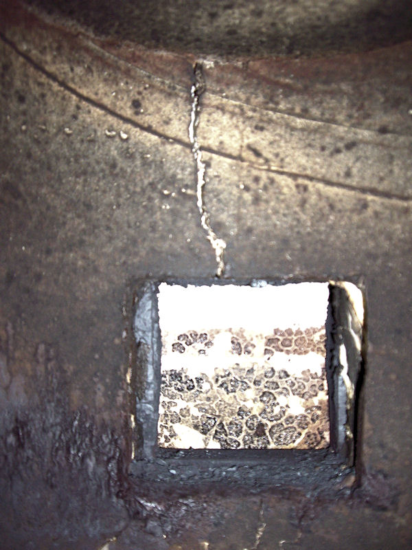
Forge Interior Top
|
|
|
|
|
|
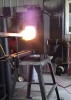
Forge at Welding Heat
|
|
|
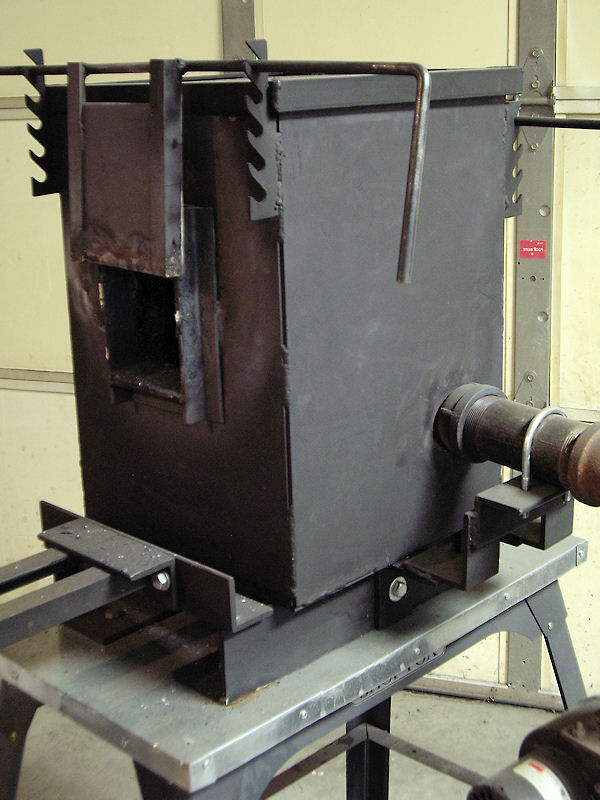
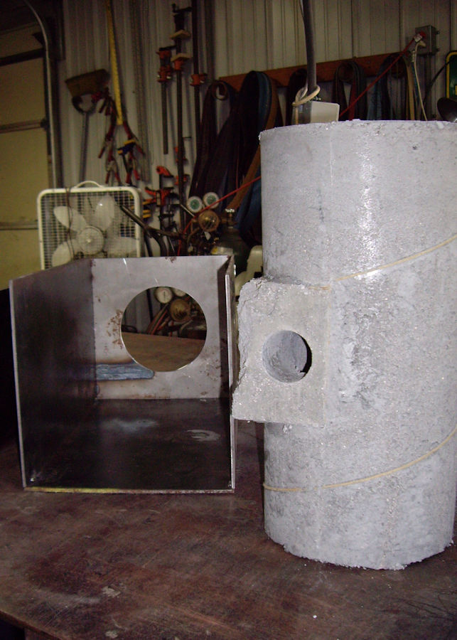
I built steel casings for my current forges, but
this is not necessary for forges of this design. I put casings
on my forges, to make it possible to move them and to also make
it easy to mount doors on them. The only down-side to a cast
forge with no steel casing, is that it is difficult to move from
where it is placed and operated. The cast forge body will crack
during use, but it will not fall apart if it has a little
support. If you try to pick it up and move it, the cast forge
body may break into pieces.
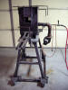
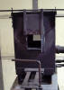
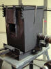
This is my large, vertical propane forge.
The cast forge body in the section above, is used in this forge.
The cast forge body is wrapped in Inswool and inserted into this
steel casing. The square casing makes it easy to mount
doors and other accessories to the forge.
I mix a thin slurry of Satanite refractory and
paint it on the ceramic wool around the door openings.
This is to protect the wool from flux during forge welding and
also to prevent wool fibers from being blown into the air.
The doors are made of .050" sheet steel, with 1/2 inch Insboard linings. The doors hang on 3/8 inch rods,
allowing them to be positioned on adjustment brackets that are
welded to the forge casing. The adjustment brackets are
cut from 1 1/4 inch angle iron.
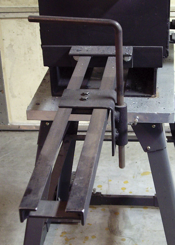
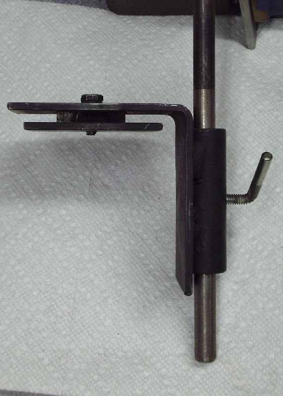
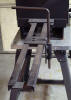
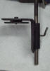
The adjustable work rest base is made of 2 pieces
of 1 inch angle iron, with spacers welded between them.
The sliding work rest can be adjusted for distance to the forge,
or removed from the base entirely. The sliding rest can
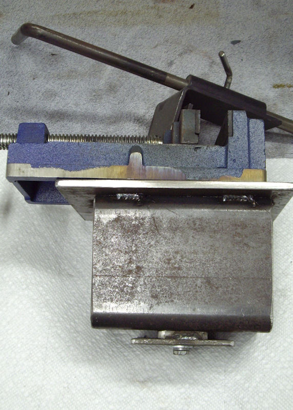
hold a variety of attachments, at adjustable heights. I
also have a drill press vice on a sliding mount, to use for
holding rods for twisting.
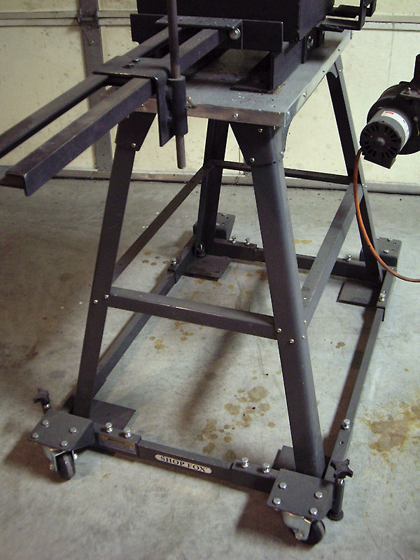
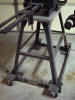
The forge stand is made of a "Shop Fox" brand
tool table and a "Shop Fox" mobile base. The table just
sets inside the mobile base. The wood table top is
overwrapped with sheet steel.
|
|
|
|
|
|
|
|
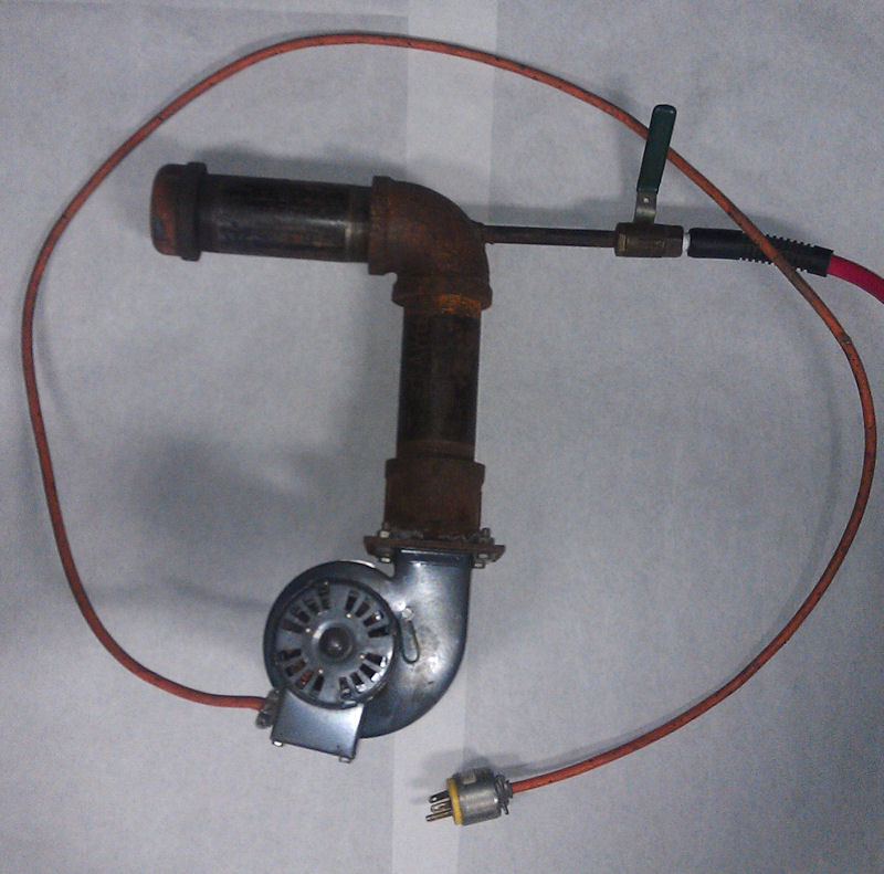
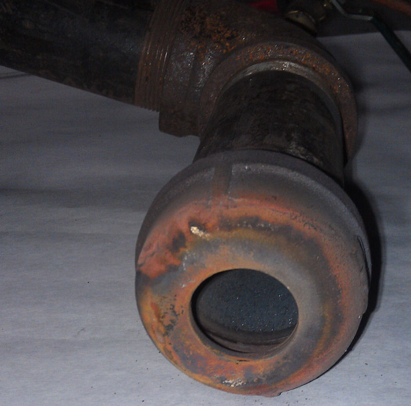
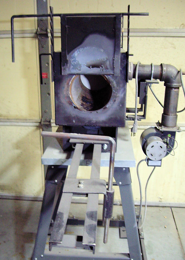
These are photos of the burner assemblies that I
build for use on my forges. The burner on the white
background is
made of 2 inch steel pipe, from the blower to the forge.
The nozzle is a pipe cap, with a hole drilled in it. The
gas inlet pipe is 1/4 in steel pipe. The gas pipe extends
about 1 inch into the elbow. There is no orifice on the
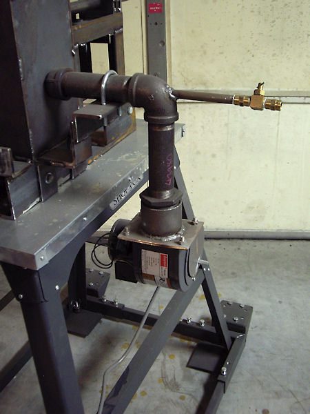
gas inlet pipe. A couple of these photos show the burner
assembly with a ball
valve for gas control. A ball valve works fine, but a needle valve
provides much more precise control of the gas flow. All of
the burners in my shop now have needle valves installed on them.
Air blast control, is by a sheet steel damper over the
intake of the blower.
These burners can be built with either larger, or
smaller pipe, depending on the size of the forge they will be
used on. The burner assembly mounted on a small forge, in
the above photo, is made of
1 1/4 inch pipe. This small burner assembly uses the same
size blower. The photo of this small burner shows a needle
valve for gas control. I have also changed my larger forge
burners to this same needle valve. A needle valve provides
much easier control of gas than does a ball valve.
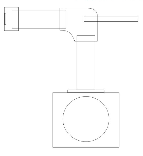
Included is a line sketch of these burner
assemblies.
When mounting the burner assembly to the forge,
the pipe cap nozzle is not inserted into the body of the forge.
The nozzle just butts up against the side of the forge.
The blast is sufficient to blow the flame into the forge.
The size of the hole drilled in the pipe cap
nozzle, is determined by the size of the forge that the burner
assembly will be used on. The hole in the cap in the photo is 1 1/4" in diameter. This
cap is installed on a large burner assembly, that is used on a
forge that has about 600 cubic inches of interior
space. Start with a smaller hole size in the cap and try the forge
out to see how long it takes to come up to heat. If it
takes too long, increase the diameter of the hole until you have
enough blast to bring the forge up to temperature in a
reasonable amount of time.
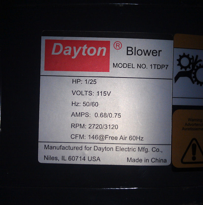
The blower that I use on these burners is a unit
that puts out 146 cubic feet of air per minute. This
blower is a Dayton, Model #1TDP7. I bought this unit from
Grainger Industrial Supply. I added the sheet metal damper to
control the air volume through the blower. |
|
|
|
|
|
|
|
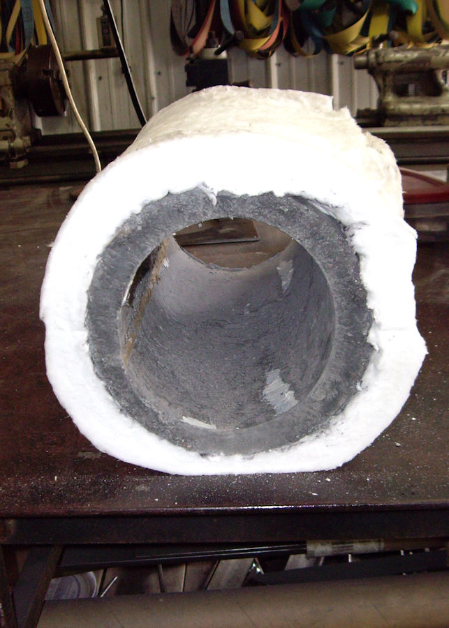
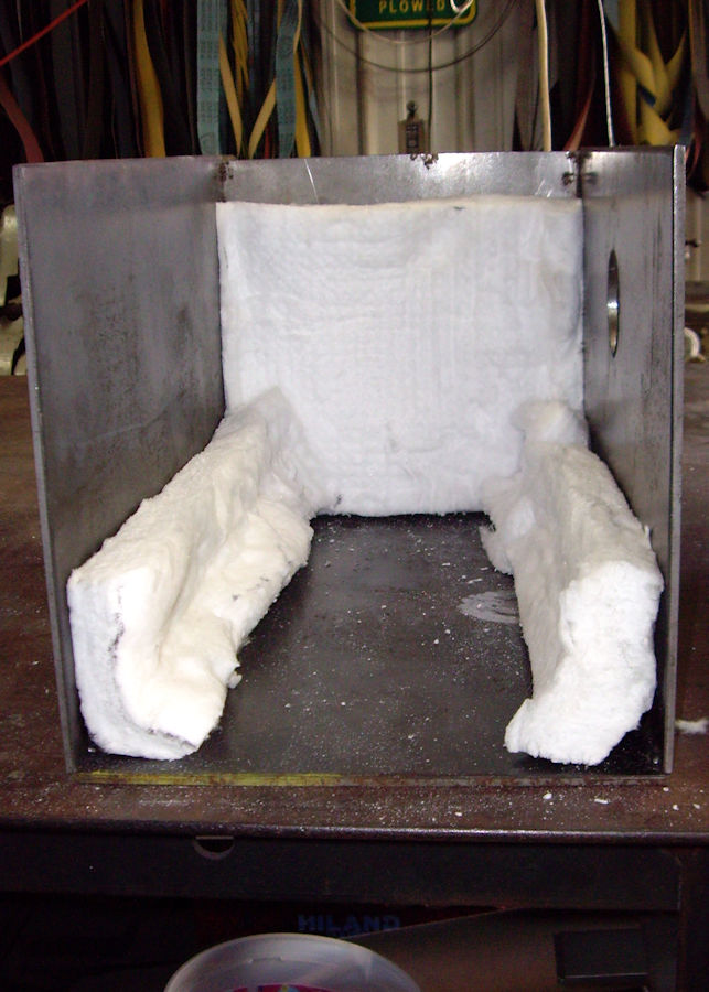
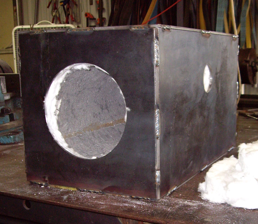
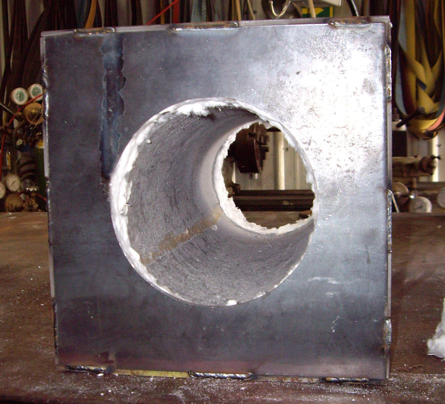
These are photos of the construction of my
horizontal forge. The construction methods for building
this horizontal forge are very similar to how the vertical forge
is made.
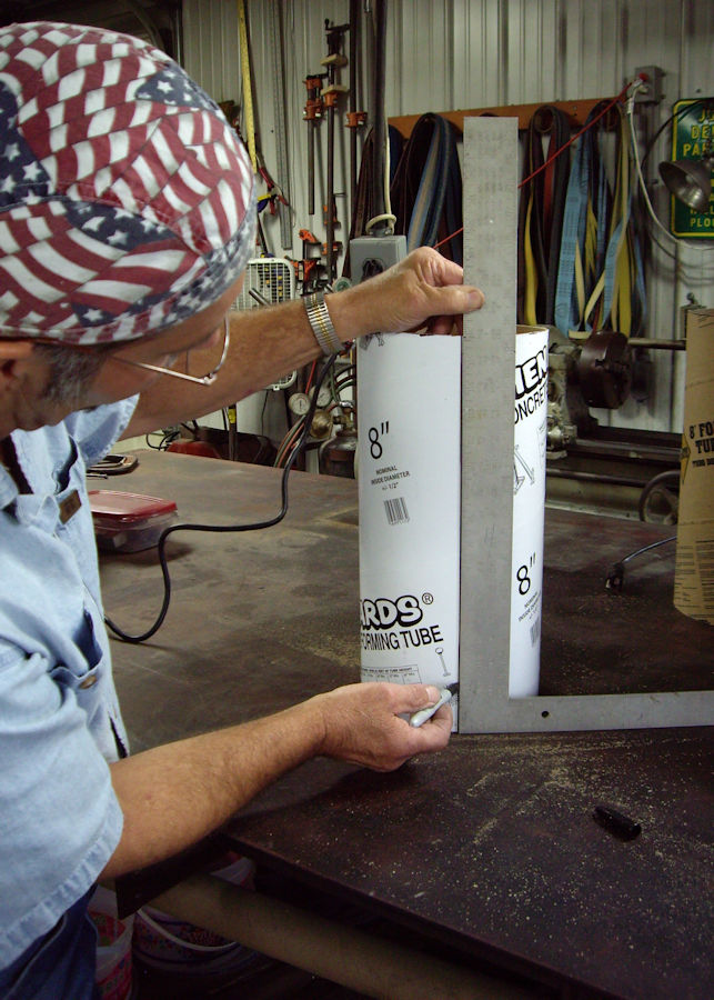
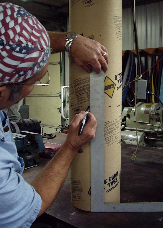
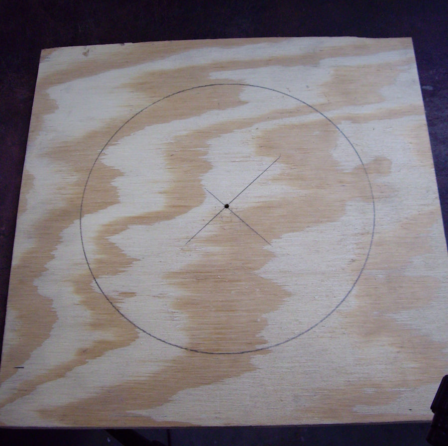
Concrete pier forms are used as inner and outer
molds for the forge body. I measure the forms by setting
them on a table and using a framing square to draw lines for
cutting. If making a vertical forge, the lines for cutting
out door openings are marked in the same way.
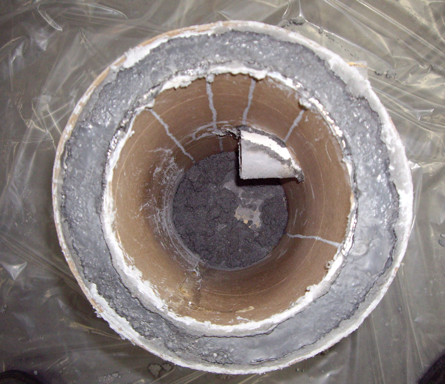
This horizontal forge body is 8 inches in outside
diameter and has a 6 inch diameter heating chamber. I have
recently found it difficult to find 8 inch and 6 inch diameter
concrete pier forms. So, I simply cut down larger pier
forms to create the needed smaller diameter forms for casting
the forges.
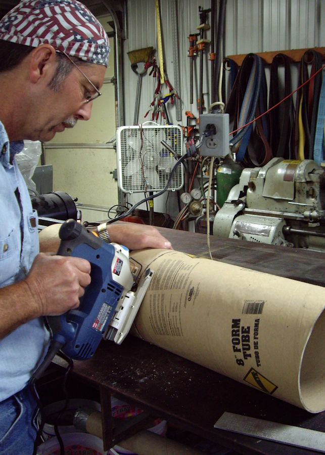
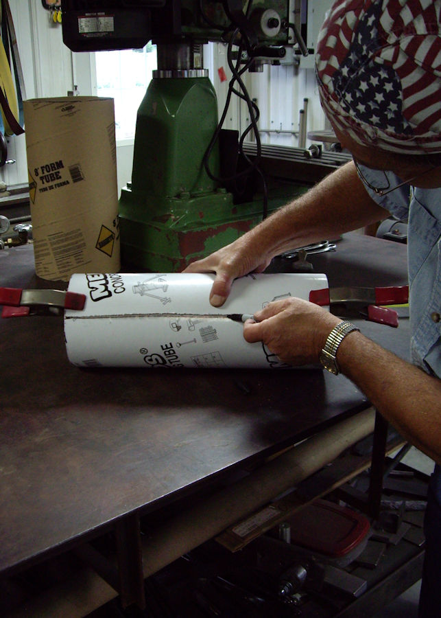
Measure the pier form and cut off any excess
material, leaving enough to create the desired diameter tube.
Leave about 2 inches to overlap and glue to create the smaller
diameter tube. Sand the edges of the tube for gluing.
I used 3M 90 spray contact adhesive for gluing the tube edges
together. After pressing the glued tube edges together, I
clamped the glued edge of the tube with a 2x4 and c-clamps.
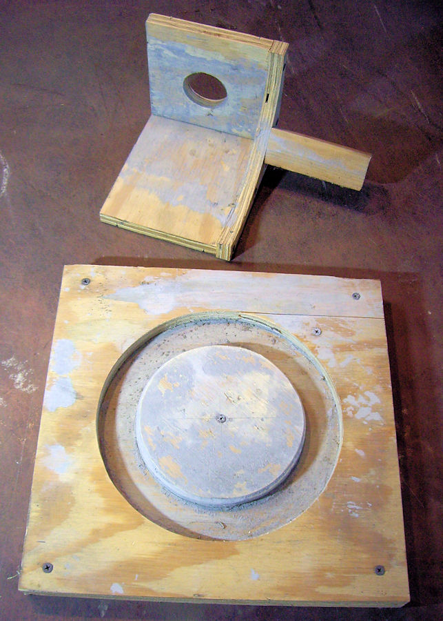
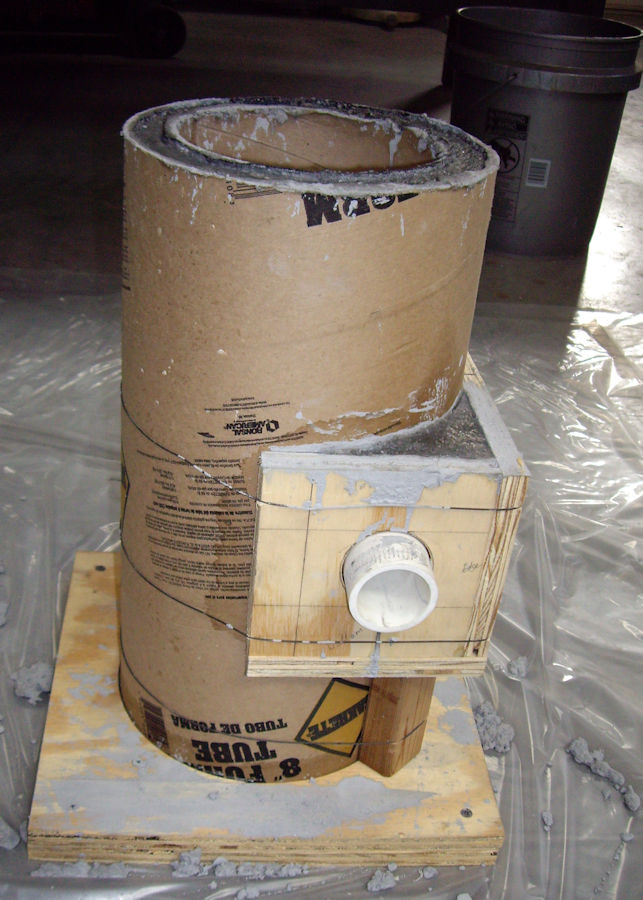
A wood base is built for locating the bottoms of
the two pier tubes for casting the forge body. The form
for shaping the burner flame inlet is simply wired to the
outside of the outer pier tube. A wood support is attached
to carry the weight of the refractory. A piece of 1 1/2"
PVC pipe is used to form the flame inlet opening.
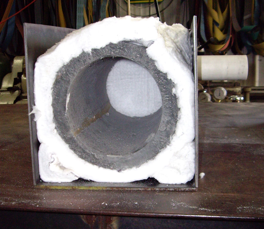
If using a steel casing around the forge body,
place the Inswool wrapped forge body into the casing before
welding the last piece of the casing in place. Only tack
weld the pieces of the steel casing. This makes it
possible to easily grind off the welds and open the casing, in
the event that the forge body needs replacement, or repair.
Or, if a piece of the casing needs to be replaced because of
oxidation damage from use.
|
|
|
|
Home
Gallery
Available
Pieces
Shop Gallery
Tutorials
Contact Info
Links Page
|